Synology DS1513+ 5-Bay NAS Review
Chris Hadley / 10 years ago
A Closer Look
Working along the top of the DS1513+, like Synology’s other systems there is no LCD display present with only a series of status LEDs found on the front of the system itself. Instead all of the warnings and detailed status information can be found through the DSM administration pages. The status and alert LEDs will flash to prompt the user that there is an issue, which they can then find through the DSM.
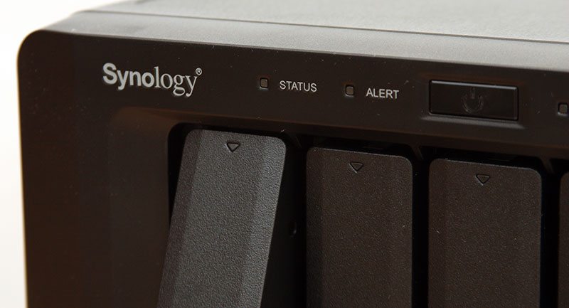
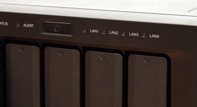
The power button is cited to the middle of the front panel with a blue LED incorporated. To the right of this are four LAN LEDs, one each for the four Ethernet ports on the rear of the system. Additionally each of the drive bay has its own status / activity LED which we can see as the small triangle at the top of each tray.
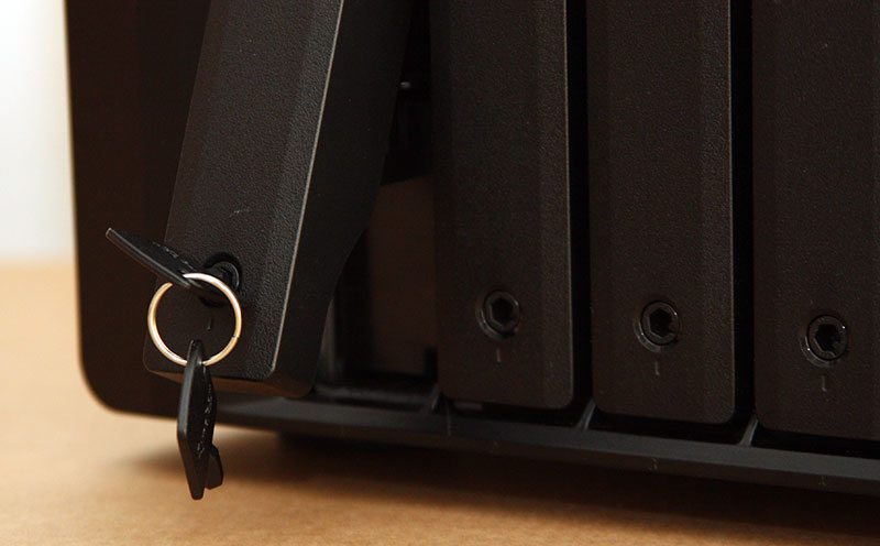
To release the drives, each of the latches pushes in and opens from its docked position allowing the drive to be pulled free. A small lock at the bottom of each latch allows the bays to be locked into position, prevented unwanted or unauthorised removal of the drives during use.
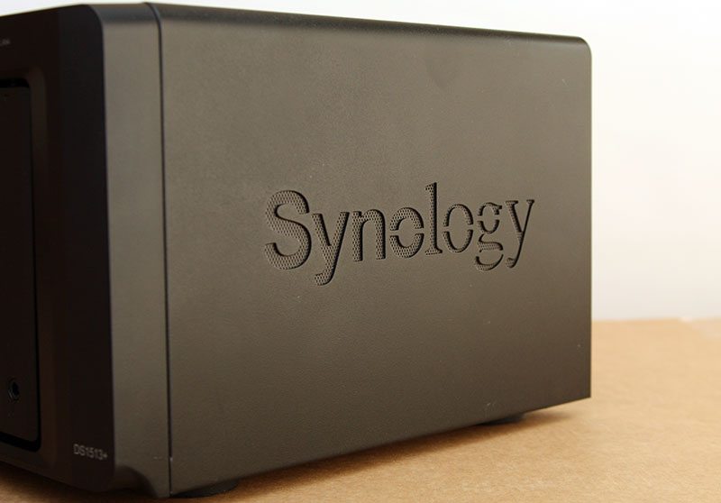
Although the drive bays have a sufficient amount of space around them to allow air to flow in and through the system, two Synology logos on either side of the chassis double up as additional vents to keep the system cool.
Turning the system around and having a look at the connectivity on offer we first note the four Ethernet ports that were noted previously, with four USB2.0 ports cited above. Below the two fans there are an additional two USB3.0 ports and two eSATA ports to either side of the system’s serial number and MAC addresses, allowing for a great amount of flexibility when connecting additional devices such as printers and additional storage for sharing out over the network such as the DX513 expansion unit.
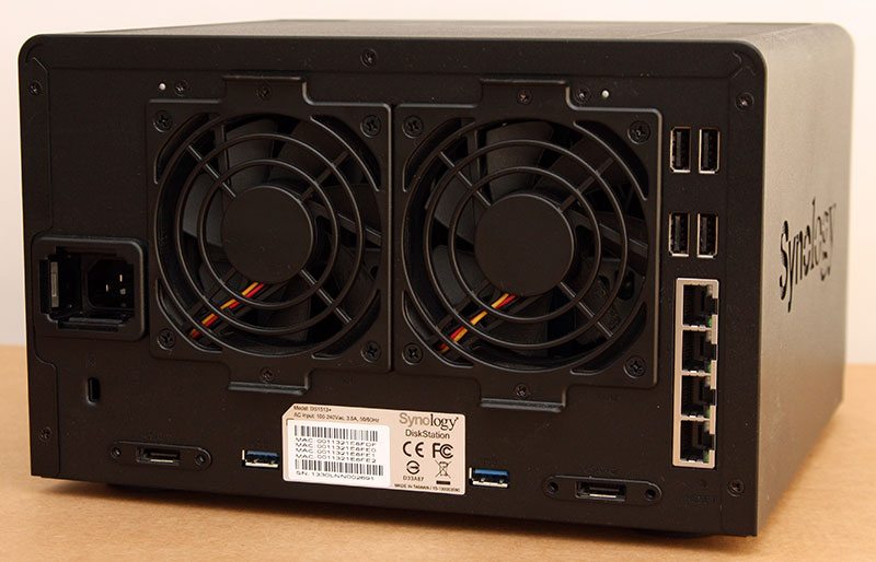
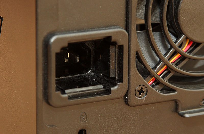
To the left of the fans we find the IEC power connector, but what we note is that this is no normal power connector. Unlike most other systems that I’ve had in for review, the power connector on here is recessed into the unit and this unusual design at this level allows for special locking power cables to be used instead of a tradition IEC power cord. The locking cord has one very simple task, which is to prevent accidental removal of the power cable when moving the unit during operation, be it to position the system in the home or office, or when moving it out to access the rear I/O.
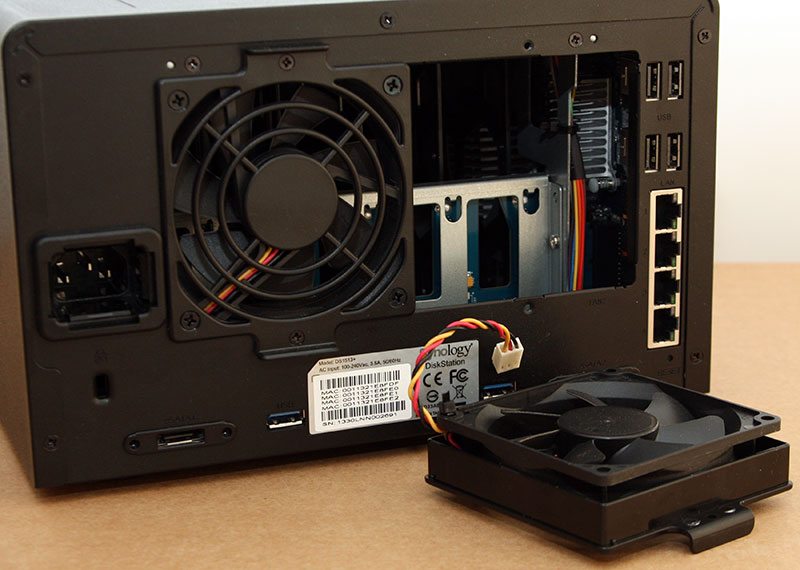
In addition to the wide range of connectivity options on offer, each of the fans can be removed in seconds via two screws. This allows the fans to be cleaned and / or replaced should they fail. By having this setup the system does not need to be shut-down or disassembled, allowing for maximum uptime.
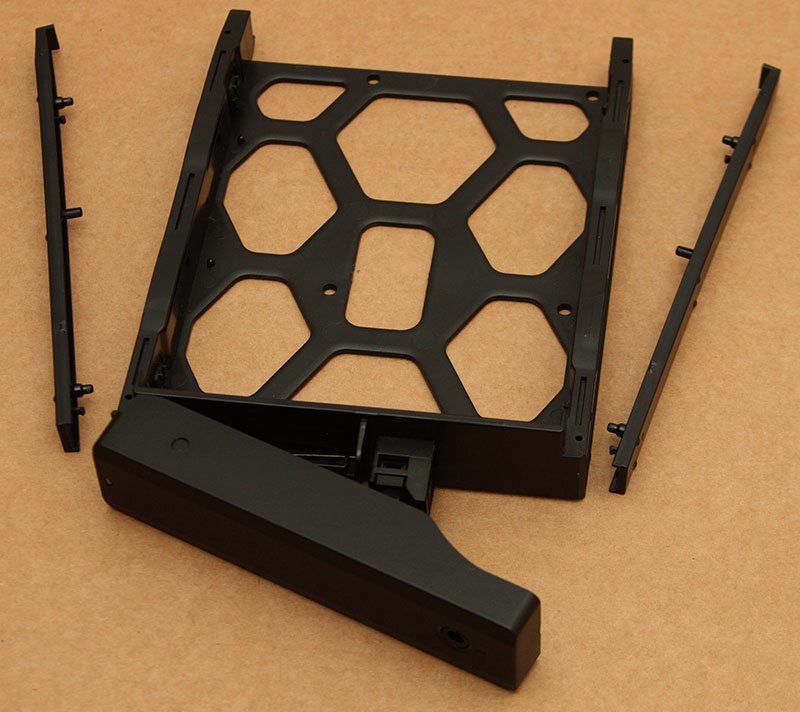
Just like the drive trays that I saw with the DS214Play, the DS1513+’s trays are fully tool free [when using 3.5″ drives], with two snap in bars on either side of each tray holding the drive in place. Four small holes on the bottom of each tray give compatibility for 2.5″ drives such as SSDs if required.
Lifting off the top cover to the system and moving on to the part where any dismantling beyond here WILL VOID YOUR WARRANTY, we can first of all see the 240W power supply that serves all the systems needs. Typically with Synology systems I have experienced external power supplies with DC power jacks, but as we move up the scale and add more drives and power, external power solutions soon become inefficient and not cost-effective, thus internal PSU’s are found.
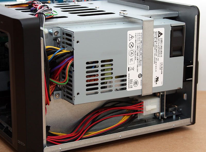
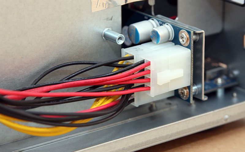
Below the PSU are two sets of cables which run to a PCB behind the drive bays, these provide power to the drives as opposed to powering them through the PCIe lane as found on some other systems.
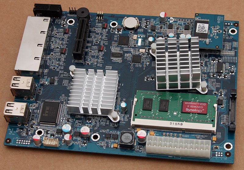
On the other side of the system we find the motherboard with a plastic cover over it to prevent any shorting out on the chassis. Towards on side of the board we find an empty SODIMM slot, allowing for an upgrade in the memory capacity from the stock 2GB up to 4GB if required.
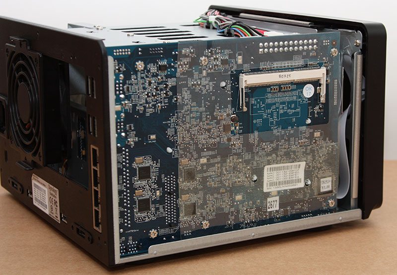
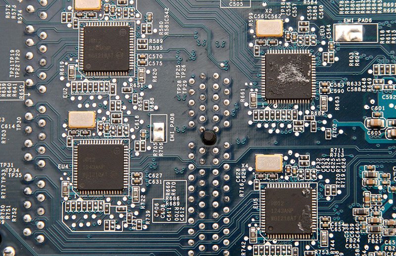
Tucked down towards the rear of the system as seen above are four small, identical chips. These are the four Intel WGI210AT server-grade Gigabit Ethernet controllers and together they can connect to individual networks or work together in a variety of link-aggregated or redundant setups.
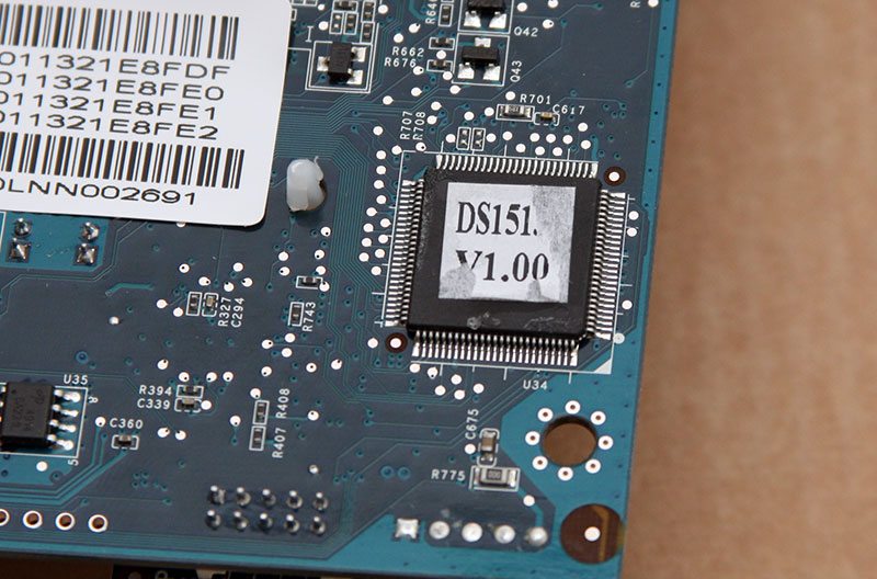
Towards the front of the PCB we lastly find the systems BIOS chip, this system running BIOS v1.00 as seen below.
Removing the motherboard from the system and turning it over to have a look at the business side of things we can clearly see that there is a whole lot more going on. Staggered in the middle of the board are two passive heatsinks and towards the bottom right of the board we find the stock 2GB 1066MHz SODIMM that comes shipped with the system.
Beside the processor we find a Silicon Image branded Sil3132 SATA 3GB/s host controller and to the left of this is a SLG8LV631V clock generator.
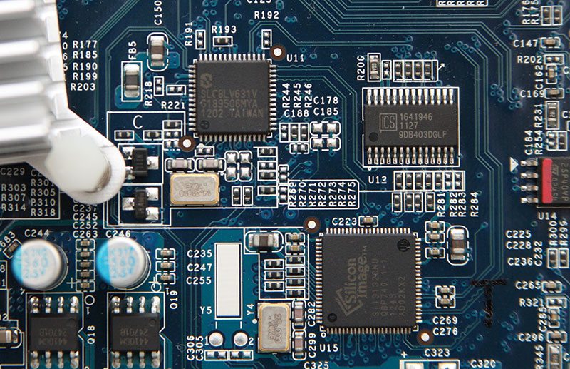
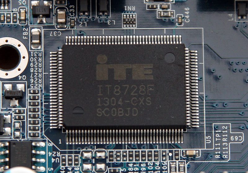
Further round the board, an ITE IT8728F package acts as the system’s hardware monitor for applications such as system temperatures.
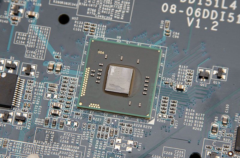
Under the first of the two heatsinks we find one of Intel’s latest dual-core 2.13GHz Atom SoC’s.
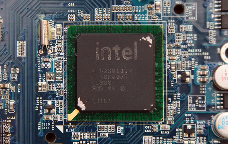
Under the second heatsink we find another Intel chip that looks a little more retro if anything and this is a 82801JR I/O Controller. Whilst this chip is able to run 6 SATA ports and a Gigabit LAN port on its own, its workload on here is much lighter with this taking care of the USB2.0 ports and eSATA interfaces.
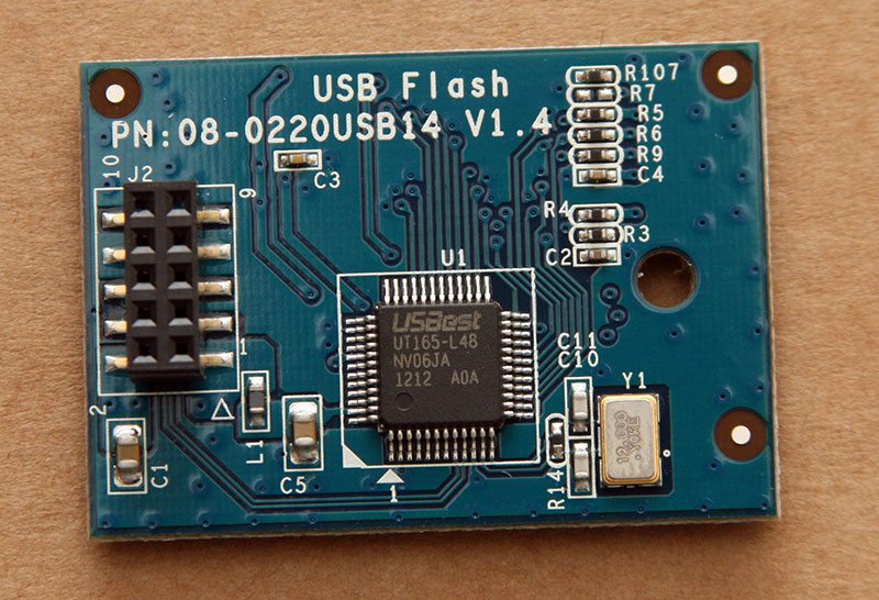
Up towards the processor we find a small daughter-board attached through a 10-pin header and looking at the underside of the board, there is no mistaking this components function. A USBest UT165-L48 USB2.0 host controller indicates that the flash memory is attached through a USB-type interface instead of being directly attached to the motherboard.
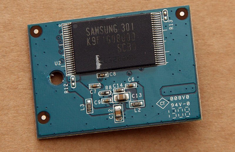
On the other side of the board a Samsung K9F4G08uoD-SCBO package provides the system with 4GB of flash storage.
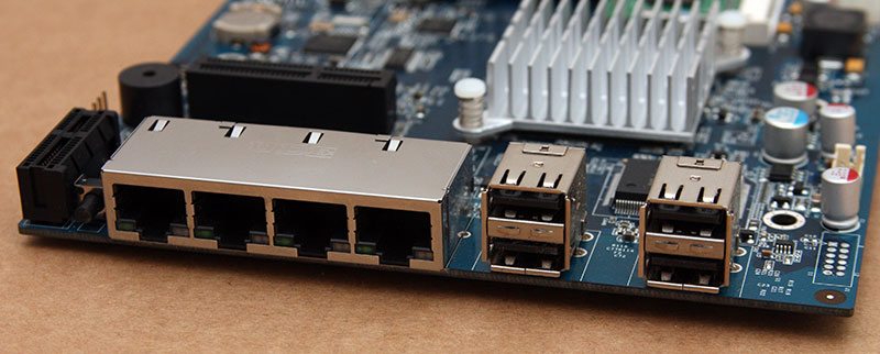
Finally towards the back of the motherboard we have the four Ethernet ports and four USB2.0 ports with a system reset switch tucked beside one of the two PCIe lanes which connect to the USB3.0 and SATA daughter-boards.
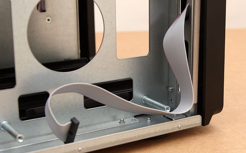
A ribbon in the front of the chassis links up the front panel and drive bay LEDs to the motherboard.
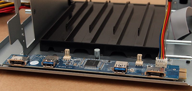
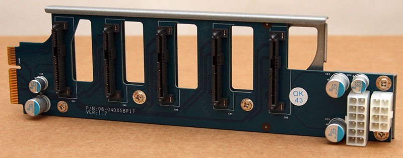
Lifting the SATA host board out of the system we can see where the two power connectors attach on one end of the board and the PCIe lane connects on the other. Holes in the PCB between the SATA headers allow air to flow through and out towards the fans.
Finally in the back of the chassis we find the USB3.0 board with a standard edition Etron USB3.0 host controller in between and the two eSATA and two 3-pin fan headers sat to either side.