Gigabyte MW51-HP0 LGA2066 C422 Motherboard Review
Bohs Hansen / 6 years ago
A Closer Look & Layout Analysis
We had a look at the general feature on the first page and now its time to take a closer look at where everything is located.
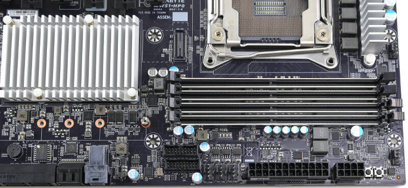
Power Connections and Onboard Buttons
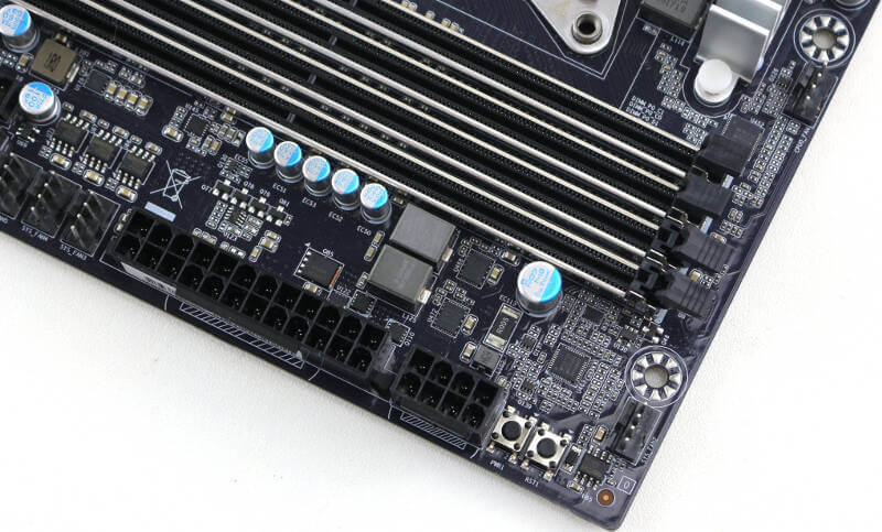
We won’t get far without power, so let us start with that. The basic power connections are located at the inner top corner of the motherboard. Here we find the 24-pin and 8-pin power connectors. So far, everything seems regular, but I can already say that it won’t stay that way. Next to the 8-pin connector, we had an onboard power button and reset button. I love it when they are present as it makes my life as a reviewer with the board on a test bench a lot easier.
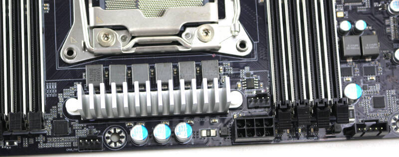
The above power connections are far from all. Next to the processor soket, we have another 8-pin power connector, making sure that there’s plenty of power for the 140W TDP processors.
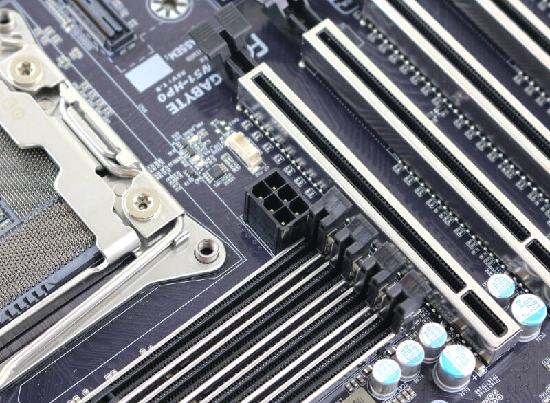
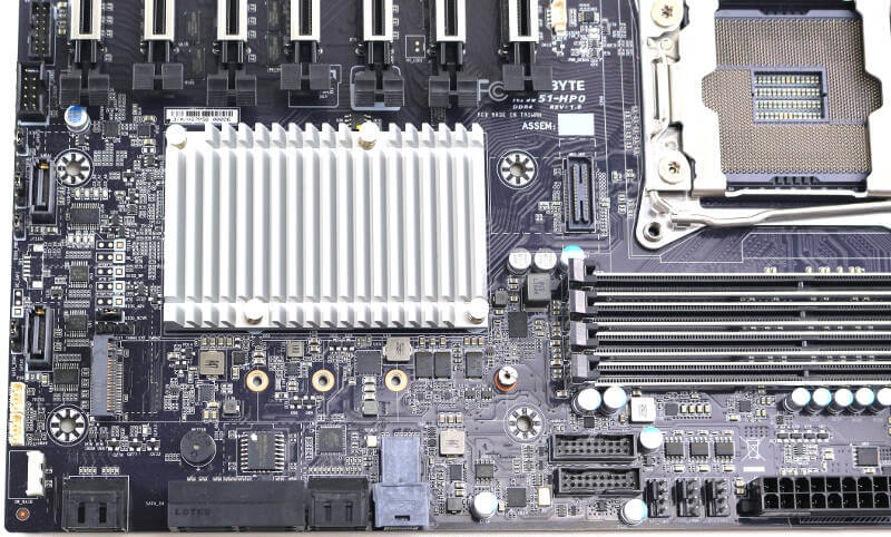
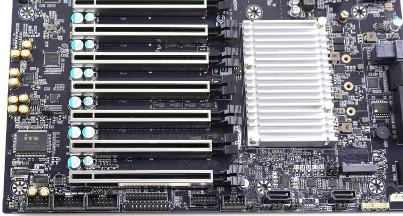
And that’s not all yet. There’s another 6-pin power connector for the PCIe slots. With 8 slots available, designed for use with high-powered add-in cards, we need to be sure that there is sufficient power available. All in all, a full setup. It’s also something which you need to consider when you pick out your power supply. You need to make sure that it has all the connectors you’ll need and not just the total power output.
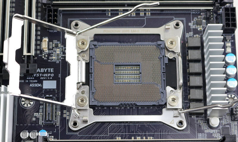
Processor and Memory Sockets
There aren’t a lot of surprises when we get to the basic sockets. The CPU socket is an LGA2066 with a square 80×80 ILM mounting systems. The standard design makes it easy to find compatible coolers and mounts.
The memory sockets are a little more interesting, even though they’re just DDR4 DIMM sockets. They are, however, reinforced just as the PCIe slots are. It also gives them a sleek look with the silver accent when compared to plain black plastic slots.
Storage Connectors and USB Headers
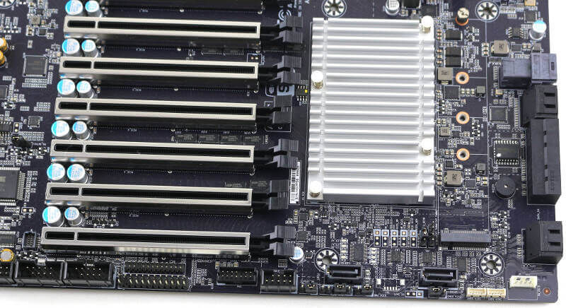
All the storage connection options are located at the bottom inner side of the motherboard. Eight of the SATA ports are facing inwards next to the U.2 connector while the last two SATA ports are located at the bottom of the board. The two separate upward-facing ports are those with DOM power support which is why they’re moved away from the rest.
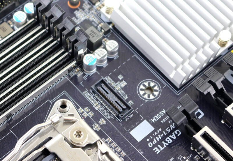
The M.2 slot is located right next to the other storage ports and there is a good reason for that. There simply isn’t room for it anywhere else. With the number of PCIe slots on the size motherboard, there’s no room to place it in between. I also quite like it when everything of the same type is located close to each other, it makes the set up go smoother.
USB isn’t technically storage connectors, but that doesn’t mean we can’t talk about them here too. In the photo below, you can spot the USB 2.0 header to the top left and the two USB 3.0 headers at the middle bottom. The USB 3.0 headers are mirrored in their connector for easy access to both.
Other Headers and Onboard Connectors
Most other headers are located at the bottom of the motherboard. From left to right in the below photo, we have the front audio connector, two COM headers, front panel and backplane headers. Those are followed by the TPM header before we get to the USB 2.0 header. Most jumpers are located here too, for easy access. Only the BIOS reset jumper is located next to the battery. I like such a setup as I don’t have to search the entire PCB for the jumper or header I’m looking for, and I can do it all without having to dig out the manual to locate the specific one I might need.
All the way to the right, we can see the two SATA SGPIO connectors followed by the VROC connector.
Gigabyte also added XDP debug connector to the board. If you don’t know what this is, you won’t need it. If you do need it, then no further explanation is needed. In case you are interested to know what such a debug tool costs, well then I can tell that it isn’t cheap. The ITP-XDP 3BR kit will set you back 3 grand.
The four chassis fan headers are all located near the top inner corner, whether that’s convienient or not will depend on your chassis. There are two more fan headers for the CPU cooler, located near the CPU socket.
Other than that, there isn’t a whole lot more to say here. There is a small onboard speaker and also a large aluminium heatsink over the chipset. Together with the reinforced slots and the black PCB, we get an overall amazing looking board of black and silver.