GIGABYTE MD71-HB0 (C622, LGA3647) Motherboard Review
Bohs Hansen / 6 years ago
A Closer Look & Layout Analysis
We had a look at the general feature on the first page and now its time to take a closer look at where everything is located.
Motherboard and CPU Power
Let us start with the most boring aspect of any motherboard and let’s get it out of the way. The power connectors. They are needed, but not especially exciting.
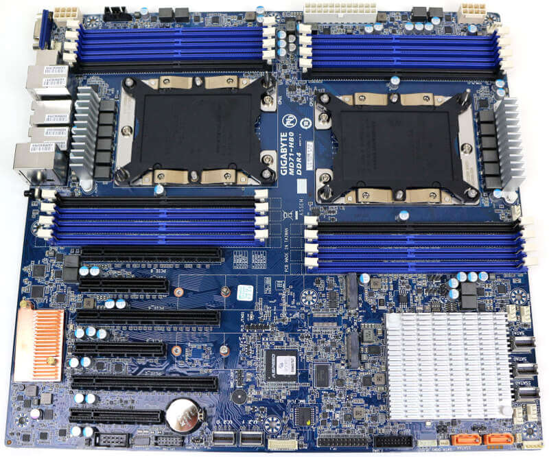
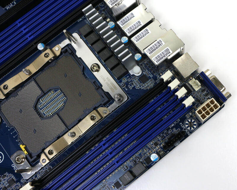
GIGABYTE’s MD71-HB0 has a 24-pin connector for the motherboard itself.
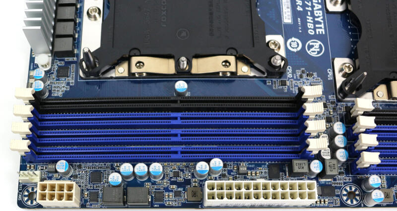
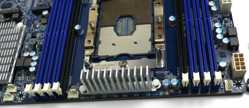
The two CPU sockets then have an 8-pin power connector each, located at each side of the top-end.
Processor and Memory Sockets
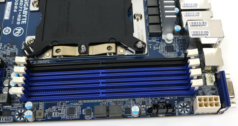
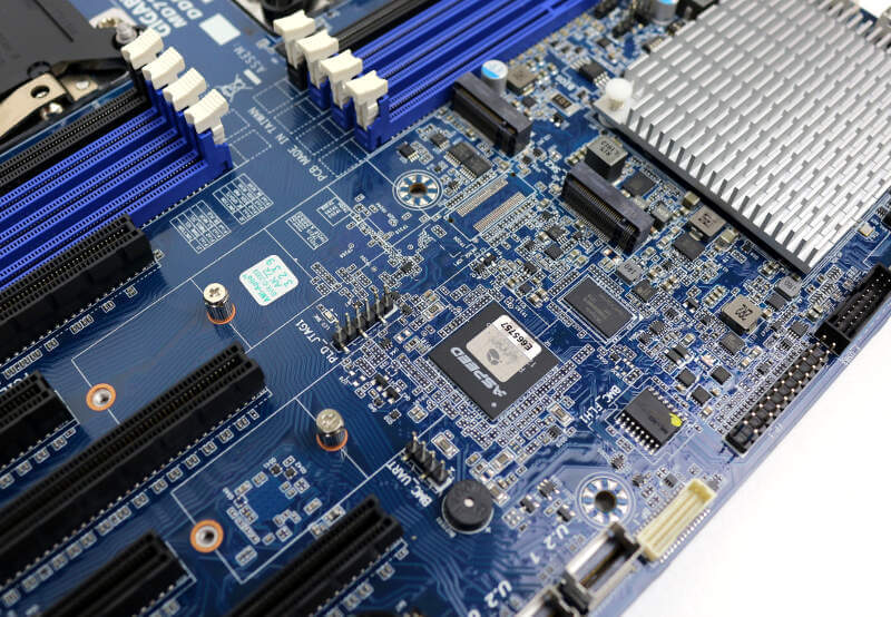
Now we’re getting to some of the juicy bits. The top of the motherboard features the two CPU sockets and 16 DIMM slots. The good thing about the placement is that the sockets won’t interfere with your PCIe cards as they would if they’d been located above each other, behind the PCIe expansion slots. The only slot that could have a few issues is the top one. Long cards could potentially conflict with the bottom memory modules behind it.
Intel’s Scalable Platform utilises a six-channel memory design which is why the colours of the DIMM slots are done as they are. You can quickly locate the proper ones to use.
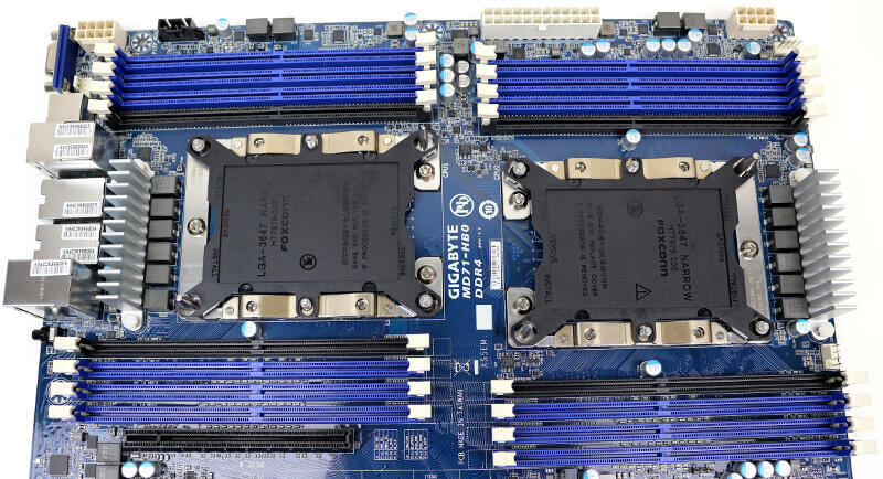
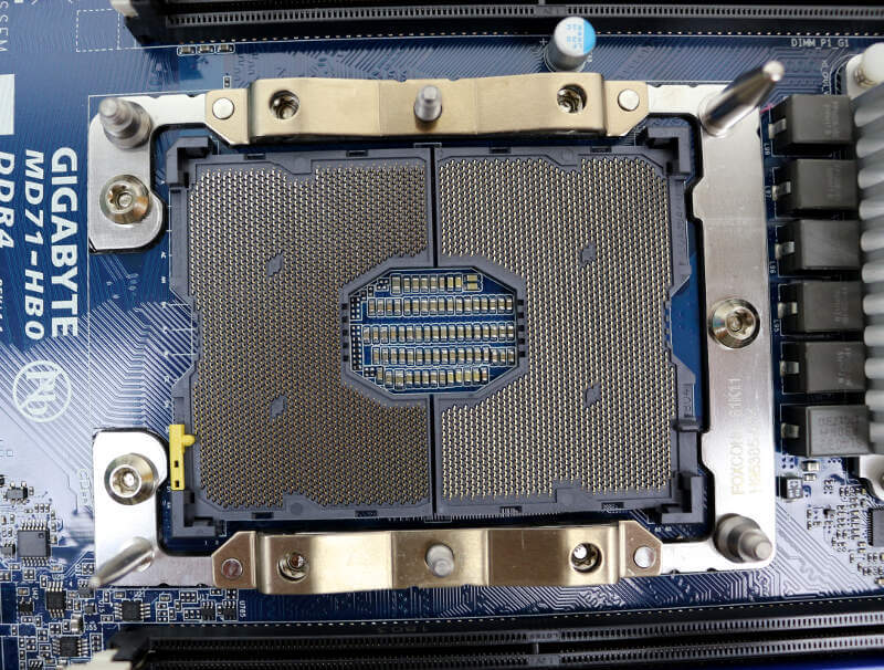
The sockets are standard LGA3647 with standard narrow ILM mounting system. Due to the orientation of the sockets, there might be issues with larger heatsinks such as those on 140mm-fan types. Most 120mm fan-based CPU coolers, or smaller, should work like a charm.
Installing LGA3647 socket CPUs is a little different that other ones, so make sure you follow the instruction of either your motherboard or cooler. Both should come with one.
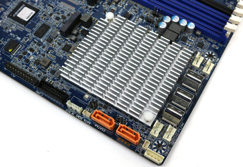
The VRMs for the two sockets are both cooled with a massiv heatsink next to them. Something we see on most server boards. All capacitors used are solid which speaks for the durability. Then again, and to be honest, I would be dissapointed with anything else these days.
PCIe Expansion Slots
The expansion slots as such as quite basic. There are no reinforcements or retention systems at the end. Easy to plug cards into and take them out again which allows for easy maintenance and upgrades. There are three PCIe x16 and three PCIe x8 slots, but you’ll need two CPUs to use them all.
The top slot, as mentioned above, could conflict with longer cards on the memory slots, but HHHL cards will fit easily.
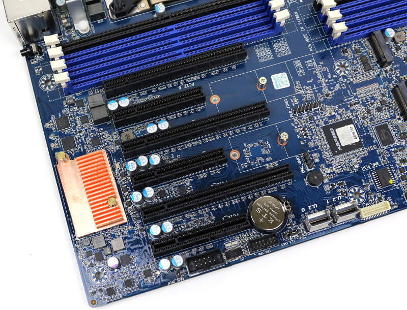
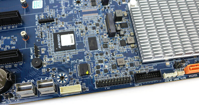
The two M.2 PCIe x4 slots are located behind the PCIe x8 slots. Both can take either a 2242, a 2280, or a 22110 module. We can also spot the ASPEED controller and its RAM chip near the bottom connector.
Storage Connectors
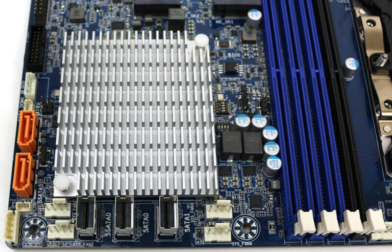
Having 2 M.2 slots, as shown above, is great. But that’s no reason to stop. Below them are two SlimSAS connectors which are intended for U.2 drives. You can attach a 32Gbps drive to each of them and expand your system with even more blazing fast storage.
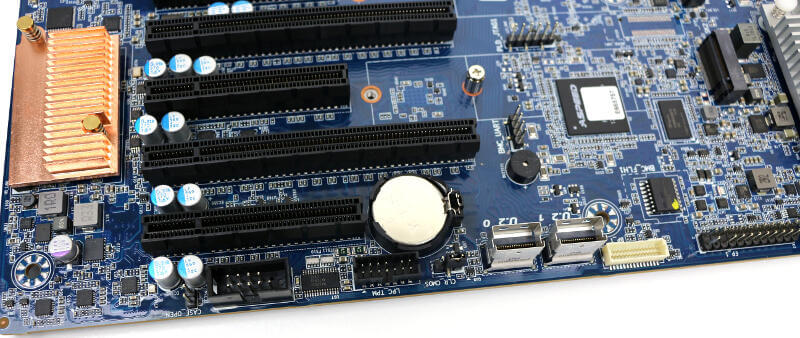
The classics aren’t as classic as you’re used to. The GIGABYTE MD71-HB0 supports up to 14 SATA3 drives. You can connect up to two SATA DOMs through the orange ports and 12 more through the three SlimSAS connectors.
More Connectors and Headers
The last headers and connectors explain themselves based on their size and shape, so I won’t bother you with a whole lot of text here.
Most headers are located at the bottom and bottom inner side of the motherboard. That includes USB header, front panel header, HDD backplane header, COM header, and more.
During this tour around the motherboard, we’re also able to spot the location of all the FAN headers.
The only one that’s tough to spot is the second CPU fan header. It is hiding up behind the BMC’s VGA port.
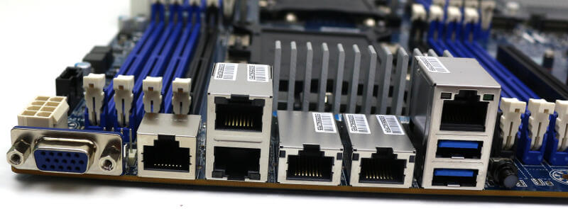
IO Area
The IO area is very simple as most of it is composed out of RJ45 ports. From left to right, you get a D-Sub VGA port, Management LAN, dual Gigabit Ethernet on top of each other, and dual 10 Gigabit Ethernet next to each other. The last section has a serial RJ45 COM port and two USB 3.0 on top of each other.